What Antenna Should I Use to Hear Jupiter?
A Beginners Guide:
In order to receive Jupiter above the roar of the galactic background
radiation, you are going to need an antenna with some gain (directionality).
The absolute minimum antenna which will work for you is a dipole cut to
the frequency of interest. With this antenna you will be able to hear some
of Jupiter's louder bursts. Dipoles are good antennas for beginners because
they are so easy to make and erect. They match easily to the feed line and
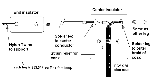
are cheap to construct. Here is how to make a dipole antenna for Jupiter:
Decide on a frequency somewhere between 18 and 22 MHz. Let's say you
pick 21 MHz. To determine the length of your dipole divide this number
(21) into 467. This will give you a length of 22.24 feet. Go to the hardware
store and buy 25 feet of #12 stranded copper wire. It doesn't matter whether
or not the wire is insulated. While you are there buy a roll of good strong
nylon twine. You are going to need a few square inches of Plexiglas for
insulators or else you can buy some commercially made insulators from your
local Radio Shack store. You need enough 50 ohm coaxial cable to get from
your antenna location to the receiver. My favorite coax for this type of
project is RG/8X minifoam. RG/58AU, sometimes used by CBer's and shortwave
listeners can be used, but it is much more lossy and susceptible to interference.
Full size RG/8 coax is awkward and heavy and better suited to transmitting
uses. You also need a connector that will match the coax to your receiver antenna jack. I don't suggest the solderless type connectors.
Measure your wire out (remember 22.24 feet for a 21 MHz antenna) and
then add 12 more inches to the total length before you cut it. You need
the extra length to make mechanical connections to the insulators. Now
cut this 23.24 foot piece of wire precisely in half. Strip away three inches
of insulation from the ends of each wire if you are using insulated wire.
 The center insulator is where you will be making the electrical connection
from the coax to each leg of the dipole. It is important that these electrical
connections do not actually support the weight of the coax. If you really
want to get fancy with this part of the antenna you can buy a commercially
made balun which will act as a center insulator and transformer
to more evenly couple the energy from the antenna into the coax. I have
not found baluns to be particularly advantageous in this application, however,
other Jupiter listeners do use them.
Pointing the Dipole
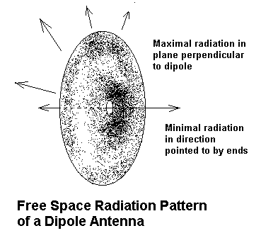
 As we said, the dipole has some directional characteristics. The radiation
pattern of a dipole in free space can be visualized as doughnut
shaped with the dipole passing through the center. The dipole is thus most
sensitive to signals arriving from directions perpendicular to its length.
It is very insensitive to signals arriving from either direction in which
the legs are pointed. Since Jupiter will trace a large arc across the sky,
lying close to the horizon in the east and west directions and higher in
the sky as it transits the meridian (north - south line) a fixed antenna
will not be always have its main beam pointed toward Jupiter except for
certain combinations of time of year and observer latitude. A single dipole
in a fixed direction will thus always present some compromises. I would
suggest that observers at mid and higher latitudes orient their dipoles
so that the legs point east-west. Observers nearer the equator will get
better coverage with a north-south orientation. A better solution is to
have two dipoles, one N/S and one E/W, which can be switched at the receiver
in order to select the one which is best pointed for the position of Jupiter
at the time of observation.
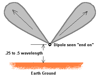
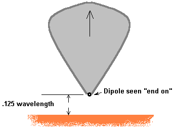
When a dipole is suspended close to the ground (less than a wavelength
high), the pattern is significantly altered. The ground below the dipole
acts as a reflector forcing the primary beam of the antenna higher as the
antenna is lowered. Many ham radio and shortwave listeners curse this effect
because it forces them to erect their antennas high above ground if they
are to effect a maximal signal towards the horizon for terrestrial communications.
For mid-latitude and lower observers of Jupiter, however, we can use this
effect to help point the beam pattern towards Jupiter, which at times can
be high above the horizon.

 As you see in the diagrams above, a height of about one eight wavelength
above ground concentrates the beam of the antenna straight up. As the antenna
is elevated the beam becomes bi-lobed and will have its greatest concentrations
at some intermediate angle. The angle is also affected by the electrical
conductivity of the ground below the antenna. Sandy, dry soil has less
affect than wet humus soil. The match between the antenna and transmission
line is also affected by the height above ground. At one eight wavelength
above a good ground the feedpoint impedance of the antenna is lowered to
about 23 ohms. This mismatch to a 50 ohm coax will cause some loss of signal,
however, in my experience, the gain in directivity outweighs this loss.
Other Antennas
The dipole has been given the most attention here because it is so inexpensive
and easy to make. As a Jupiter antenna its performance is, however, somewhat
marginal. You can really increase your chances of success by using a more
directional antenna which can be steered in direction.
A dual
Dipole array has been designed for the Radio-Jove project that has been
found to be effective and inexpensive.
A three or four
element Yagi antenna is perhaps the most practical choice. Several commercially
produced Yagi antennas for the 15 meter (21 MHz) ham band are available.
These have price tags of about two to three hundred dollars. You can find
suppliers here on the internet. The first time I remember hearing Jupiter
was on a radio quiet morning using a home made 2 element Yagi antenna for 15 meters.
The signal bursts were at least 12 dB above the background noise. The design
for the antenna was taken from an old ARRL handbook and cost less than
$50 to build. A small light design like this can be easily rotated with
a TV antenna rotator. If you really want to get fancy, you can use a second
rotator for elevation control, though as with the dipole, it is also possible
to affect the beam take off angle by adjusting the height of the antenna
above ground.
A two element cubical quad antenna has also been suggested as a Jupiter
antenna. Plans for these and other beam antennas are available in the ARRL
Antenna Handbook.
The Moxon
antenna hold promise as a Jupiter antenna.
I built a Log Periodic Dipole
Array for spectral work on Jupiter. This antenna covers 17 to 30 MHz
and has performed well.
Antennas Not to Use!
There have been a number of publications of articles suggesting the use
of a small loop antenna placed close to a screen reflector. This antenna has not
in my mind been proven to be good for Jupiter. Computer modeling shows that
these antennas would have very little chance of success.
Occasionally someone will also ask if is possible to receive Jupiter
on an "active antenna" with a small whip element. This will not work. These
devices are simply preamplifiers matched to these little extendable whips.
It will simply swamp your receiver with background noise which it receives
equally well from all directions except up.
HOME
| BEGINNERS | JUPITER
| SOLAR | PULSARS
| PROJECTS | FAQ
| BOOKS | SOFTWARE
| SUPPORT | ORDERING
| LINKS


