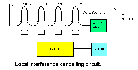
Local RF Interference Canceller
The simple arrangement described here is sometimes effective at canceling a single source of RF interference to radio astronomy observations. There
is no claim to originality here. Circuits like this have been used almost
since the beginnings of radio technology for this purpose. Broadband interference
in urban environments is pervasive. It is the amateur radio astronomers
worst enemy! The sources of this type of interference are too numerous
to enumerate but include electric motors, neon signs, dimmers, and power
line insulators. You can't usually tune around it unless you go to microwave
frequencies, but it is possible to cancel it's effects when dealing with
a single nearby source.
 The diagram above shows a simple arrangement whereby the noise canceling is accomplished. A signal from a separate antenna is adjusted so that it
is 180 degrees out of phase with the desired signal. The signal is then
adjusted in amplitude so that it is close to the amplitude of the interference
signal as it is received by the main antenna. The signals are then combined
prior to input to the receiver.
Phase adjustment is accomplished by adding lengths of coax cut to the
proper length in line with the signal from the "sense" antenna. This antenna
can be any 50 ohm antenna, but I chose to use a vertical dipole because
I felt it would be most inclined to receive local interference which is
often vertically polarized and would be unlikely to couple with the horizontally
polarized yagi antenna used for radio astronomy. The length of each piece
of coax was calculated by choosing a multiple of 1/16 of the desired signal
wavelength and multiplying by the velocity factor of the line (.67 for
RG8-X). The coax is switched in or out of the circuit with double pole
double throw slide switches.
 To accomplish amplitude adjustment I used a simple potentiometer divider.
This was only possible because the signals I am dealing with 38 MHz are
very strong and mismatches aren't very important. A better way to do it
would be to use a step attenuator which matches the impedance of the coax.
In some cases, you might even need to amplify the noise signal to achieve a level equal to that received by the main antenna. Combining the signals
should be done in an isolated port combiner. Again, I was able to fudge
here because of the intense signal strength of my cosmic source signals.
I simply combined the signals in a T adapter. The unit is housed in an
unclosed aluminum chassis. The longer pieces of coax are taped into loops
and secured to the chassis to prevent them from placing a strain on the
slide switches. Much more care should be exercised when dealing with higher
frequencies.

The picture above shows the noise spikes clearly visible on an oscillograph
of audio taken from the receiver before addition of the canceling device.
The spikes are so strong that they are being clipped by the receiver.

The above oscillograph shows that the spikes were completely eliminated
by the canceller. No reduction in desired signal sensitivity was noticed,
but then again we are talking about a very broad beamed main antenna pointing
at a very strong signal source. One limitation of this approach is that
a separate canceller is needed for each frequency band of interest because
the phase shifter is frequency dependent. Also, only one source is of interference
is canceled except in the very unlikely situation where two sources lie
at the same distance from the sense antenna AND the main antenna. I suppose
you could use two canceling units and combine all three signals if you
had to.
HOME
| BEGINNERS | JUPITER
| SOLAR | PULSARS
| PROJECTS | FAQ
| BOOKS | SOFTWARE
| SUPPORT | ORDERING
| LINKS


