The LabJack U3
With RSPII, internal support begins for the popular LabJack ADC models. Currently the U3-LV and U12 models are supported. Both devices connect to the computer using USB. The old parallel port is rapidly disappearing from computers and so it was felt that some sort of relatively inexpensive USB device should be supported. These devices are very flexible and support numerous outputs as well as the ADC inputs. The Pro version of RSPII allows you to actually control some of these outputs based upon data Triggers. This provides a way to actively use the incoming data to affect real world actions such as turning on or off electrical devices.
To read more about or purchase the LabJack U3-LV and U12 devices visit LabJack.com.
If you use either of these devices you need to configure them for use with
RSPII using the appropriate panels of the ADC Set Up window. To get to
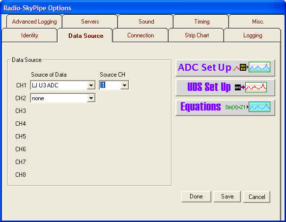
this window go to Options / Data Source and click on the ![]() button. A tabbed window appears. Select U3 or U12 panels as needed.
button. A tabbed window appears. Select U3 or U12 panels as needed.

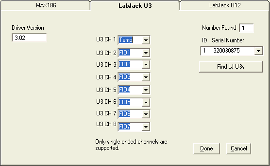
Currently only single ended channels are supported with the U3. This configuration panel allows you to map which of the possible inputs will be assigned to which U3 channel. This may be a bit confusing so lets elaborate. There are 8 possible data channels that can be used on a RSPII strip chart. Think of these channels as as individual pens on a strip chart recorder. Whatever is connected to that pen will draw a line in the pen's color. When we select the Data Source on the Data Source page for each pen channel . We select a device type (MAX186, LJ U3, etc) and we select a device channel from that device (if more than one is available) to feed the charts pen channel. Because the LabJack devices have more than 8 possible device channels we have to select a limit of 8 channels that will be used. This is what we are doing on the ADC Set Up panel above.
Notice that for U3 CH 1 we have selected the internal temperature channel. Now if on the Data Source panel below we select U3 and CH 1 we will have the U3 temperature sensor attached to the channel 1 pen channel of the chart. If we had selected U3 and CH6 we would have the FIO5 channel of the U3 device connected to the channel 1 pen of the chart.

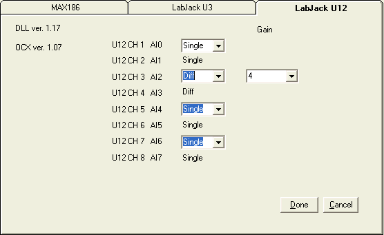
The U12 device configuration shown below.

The U12 analog inputs use pins AI0 through AI7 on the box. These are currently the only choices for inputs to RSPII. However, there differential inputs are supported in RSPII for the U12 and so the even numbered channels you can select Single or Differential from the drop-down boxes next to these pin numbers. In differential mode the pins work in pairs and so if select Diff on pin A12 then the pin below it automatically reverts to Diff also. In addition, a Gain setting becomes available for the differential pair of inputs. This controls the gain of the programmable gain amplifier in the U12. See the U12 documentation for more information. In the example above you would choose U12 channel 3 to map to your chart pen channel of choice if you wanted to access the differential pair as your data source.