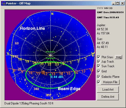
The sky map shows a "beneath the dome" view of the sky with the central point representing the zenith, (straight up). The map has some interesting features, including stars with selectable limiting magnitude down to magnitude 5, the time marked paths of Jupiter and/or the Sun, and antenna coverage patterns. The map makes it easier to determine which antenna configuration is best for a particular time.

Each item can be selectively displayed including the grid. The mag button brings up an input box in which you can select the limiting magnitude for the stars. (See if you can pick out the constellations.) You may also display the plane of the Milky Way on the map by selecting the Galactic Plane check box. This is important because along the galactic plane and especially near galactic longitude 0, you can expect higher background radio noise levels. The Grid can be turned off and on. You can ascertain any position on the chart simply by moving the mouse over it and watching the title bar of the window.
The green ellipse represents the 3 dB points in the antenna pattern. Inside of the ellipses is thus within 3dB of the strongest signal available from the antenna. A central mark + and numerical designation (8.44 dBi in the example above) shows the beam center and the strength of the antenna beam at that point when compared to a hypothetical antenna that would radiate in all directions. The green bars near the center represent the orientation of the dipoles.

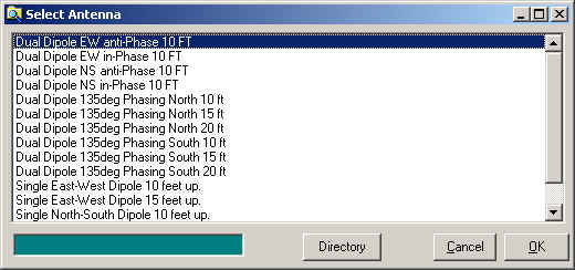
If you press the Load Ant button you will receive the Select Antenna box shown above. This box lists all of the defined antennas in your Antenna directory by the verbal description given to each. This is much easier than trying to decipher an antenna file name. You may change your default Antenna File directory, but usually it will be under the application directory. For example: C:\Program Files\Radio Jupiter Pro 3\Antennas
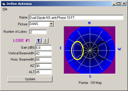
The antenna files are text files and could be edited manually but a tool is provided to make working with them easy. You may define new antennas or modify the existing antenna pattern information by using the Define Antenna Tool. Press the Define Ant button from the Sky Map to get there.

Antennas are defined as a collection of ellipse shapes projected on the dome of the sky. Some antenna patterns have only one major "lobe" and thus may be adequately defined as a single ellipse. Others have multiple main lobes or significant "sidelobes" that should also be defined to give a more accurate picture of where the antenna is receiving from. When defining a new antenna:
Click File\New
Give the antenna a descriptive Name.
There are a few antenna element arrangement "pictures" to chose from. If one exists for your antenna (dipoles and dual dipoles presently) then select one.
Enter the number of lobes you wish to define. You must have at least one.
If known, enter the gain in dBi (decibels over an isotropic antenna) for the lobe. Enter 0 if unknown.
Enter the Vertical and Horizontal beamwidths of the antenna lobe in degrees.
Apply AZ (Azimuth) and ALT (Altitude or Elevation) coordinates for the lobe.
Press the Update button.
If you need to define additional lobes, do so using the arrows to move between lobe definitions. Be sure to press Update each time.
Press File/ Save Antenna to save your creation. use the ANT file extension and save the file where you are keeping you other antenna definitions.
Horizon Files
New with Version 3.1 is the ability to define your local horizon on the Sky Map. This feature is of interest to users who have blockages along their horizons. Someone living on a mountainside or next to a large building can plot those objects on the map to better simulate the view of the sky that is available to them at that location. The horizon must be defined in a simple text file in a format that is common to the Radio Eyes program or Carte du Ceil. The format is a list of Azimuth and Elevation values that could be input using Notepad or some other text editor. An example file is shown below:
# File format :
# Azimuth(integer) Altitude
#
# Be sure to begin at the North horizon (azimuth 0)
# Intermediate missing values are interpolated
0 0.0
10 0.0
20 0.0
30 0.0
40 5.3
50 4.8
60 5.3
70 8.5
80 10.7
90 12.8
100 10.1
110 9.1
120 7.5
130 0.0
360 0.0
Lines that begin with # are ignored. Begin at 0 degrees azimuth (North) and supply on each line a azimuth value followed by a space and an elevation value that corresponds to the horizon. Areas between defined azimuth points are interpolated so you do not have to supply every degree of azimuth. If you own Radio Eyes, you will find it has a tool to help you graphically create horizon files. You can point Radio Jupiter to the Radio Eyes horizon file if you wish.