Radio-SkyPipe Help
Check the orientation of the following components to make sure you have not put them in "backwards":
With no power applied to the circuit, inspect each solder connection on the board and on all connectors. Good solder joints normally have a shiny silver appearance. A "cold" solder joint will have a dull gray appearance. If you find solder connections that you suspect may be "cold", carefully reheat them with your soldering iron until they appear to liquefy. Also look for solder "bridges" between solder pads. These usually occur when too much solder is used or when the soldering iron accidentally touches adjacent pads during initial assembly. To fix solder bridges you can use a product called "solder wick", a copper braid that sucks up hot solder by capillary action. Lay the clean end of the solder wick across the pads from which you want to remove the solder bridge. heat the solder wick with a bit of pressure from the tip of the soldering iron until the solder melts and flows onto the wick. You may have to go back and touch up the connections with a bit of solder if you remove too much.
With the computer disconnected and power applied to the circuit, check the following voltages:
Not all commercial printer cables pass all 25 conductors. Test your printer cable using an ohm-meter to make sure you gave continuity on the pins that are use by the circuit.
You may test to see if the computer is trying to talk to the ADC circuit using a pulse capturing logic probe or an oscilloscope. You should be able to detect pulses on the SCLK (pin 19) , CS (pin 18) , and Din (pin 17) pins of the ADC chip when the program is actively trying to collect data from the ADC.
In order for your computer to successfully communicate with the MAX186 ADC you must:
Versions of Radio-SkyPipe prior to version 1.2.X did not support ADC usage on Windows 2000 or Windows Xp. You should update to the most recent version of Radio-SkyPipe before continuing this troubleshooting exercise.
Configure Radio-SkyPipe to use the MAX186 ADC by selecting Options and then the Data Source tab.
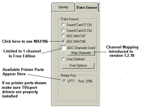
If you are using a version of Radio-SkyPipe that is older than version 1.2.10, your Data Source panel will appear somewhat different than the above image. On this option panel:
Save your options before exiting from this panel.
Support of access to the printer ports on all Windows operating systems requires the installation of a special set of drivers on your PC. Normally, these drivers are installed during the full installation of Radio-SkyPipe. In some cases, however, it may be necessary to these drivers as a separate process. If the drivers are not successfully installed on your PC, you may get an error box that tells you this, and/or no printer ports will appear in the Printer Port selection box on the Options/ Data Source panel.
You may try to install the drivers manually by running the Install Drivers program that appears in your Programs menu under Radio-SkyPipe. Make sure Radio-SkyPipe is not running when you attempt the installation of the drivers. The name of this executable file is InstallTVicport.exe and should be located in the directory where you installed Radio-SkyPipe. In Windows 2000/NT you should be logged on as administrator before attempting to install these drivers.
After running the driver installer, reboot your computer.
If the running the Install Drivers program does not work, you may attempt to install the drivers manually. Manual installation is as follows (assumes installation of Radio-SkyPipe in the C:\Program Files\SkyPipe1 directory :
Windows 2000/NT/Xp
1. In Windows 2000/NT you must be logged on as an administrator.
2. Open a Windows Explorer (Not Internet Explorer!) window.
3. Open the C:\Program Files\SkyPipe1 directory
4. Find the file setup_NT.inf
5. Right Click on the file and select Install from the drop-down menu.
6. Reboot your computer.
Windows 95/98/Me
1. Open a Windows Explorer (Not Internet Explorer!) window.
2. Open the C:\Program Files\SkyPipe1 directory
3. Find the file setup_9X.inf
4. Right Click on the file and select Install from the drop-down menu.
5. Reboot your computer.
Are you expecting your ADC to do something it is not designed to do? The ADC is a very powerful device but it has internal limitations and is further restricted by the software which drives it. The ADC reads a voltage applied to one of it's inputs and converts the measurement into a digital form which it then sends back to the computer.
Radio-SkyPipe's application of the ADC is for relatively low data rates. On a very fast computer, data rates of greater than 100 samples/sec should not be expected. Sound signals, like those from a radio change voltage much faster than the ADC can register. Also, the sound output voltage may go "negative", that is, below zero volts during half of its cycle. You thus cannot send a sound signal directly to an ADC!!! If you want to measure sound signals you may either use the SkyPipe sound card data source option or you must first condition the sound signal before applying it to the ADC.
The two circuits shown above will translate the audio (AC) signal into a DC voltage which the AtoD can follow. The upper circuit is best for audio sources of low impedance such as external speaker circuits of 16 ohms or less. The lower version without the transformer will work with high impedance outputs. The diodes in both circuits are standard silicon switching diodes like 1N914s . The capacitor C and resistor R in each circuit are determined by the amount of smoothing or "integration" you want to apply to the signal. Increasing the value of either C or R will increase the integration. A good starting value might be a 10 microfarad electrolytic capacitor for C and a 100 kilohm resistor for R.
One limitation of the above circuits is that neither will supply quite the voltages necessary to take advantage of the full input range of the ADC chip. A small op amp type amplifier just prior to the ADC input could be used to take advantage of the ADC's full 0 to 4.095V range. A very nice commercial unit with two sensitive op amp detectors and a MAX186 ADC is available from us.
Help Index | Radio-Sky Publishing Home